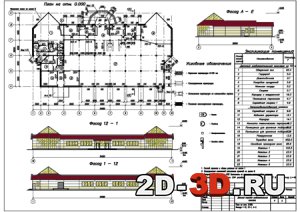
Torgovo Razvlekateljnij Centr Dwg
Create 3D Inventor parts associative to the source 2D geometry created in AutoCAD. • Insert an AutoCAD DWG file as an associative DWG: • In a part file: • Manage tab Insert panel Import • 3D Model tab Create panel Import • In an assembly file: • Assemble tab Component panel Place • In the Place Component dialog box, select a DWG file and click Open. For more information see • In a 2D sketch, click a face or work plane to set the sketch plane.
• Click Sketch tab Create panel Project DWG Geometry. • Select the geometry to project. Select one of 3 options: • Single geometry • Connected geometry: Closed loop and/or open loop. • Geometry block. Note: You can project DWG geometry in another part that is also open for edit in an assembly. • When done, select Cancel or right-click and select OK. Pepa prase crtani na srpskom.
On the 3D Model tab, extrude the DWG geometry and create 3D features as desired. In an assembly file, you can use the Joint, Constrain, and Assemble commands to create relationships between a DWG underlay block and a part. You can work on DWG geometry in an assembly file at the same time as working on the same DWG geometry in a part file.
LKS [Lembar Kerja Siswa] Kelas 1, 2, 3, 4, 5, 6 SD/MI - KTSP - Pada dasarnya merupakan sebuah kumpulan soal-soal yang terdiri dari beberapa mata pelajaran mulai dari. Lks matematika sd kelas 6. Ane punya beberapa LKS dari kelas 1 sampai kelas 6 SD yaaaa lumayan bisa dijadikan contoh buat latihan anak-anak bu.pak. Seperti biasa cara downloadnya tinggal klik aja terus, pilih save as atau unduh sebagai, terus save dah ke komputer or laptop ibu n bapak guru sekalian. Download LKS (Lembar Kerja Siswa) SD Lengkap Kelas 1, 2, 3, 4, 5, 6 Semester 2 - Selamat berjumpa kembali dengan blog kami www.librarypendidikan.com.Pada kesempatan. Ulasan: soal lks matematika kelas 6 sd. Contoh File Berikut ini adalah kumpulan dari berbagi sumber tentang soal lks matematika kelas 6 sd yang bisa bapak/ibu gunakan dan diunduh secara gratis dengan menekan tombol download biru dibawah ini.
• On the 3D Model tab, extrude the DWG geometry and create 3D features as desired. • In an assembly file, you can use the Joint, Constrain, and Assemble commands to create relationships between a DWG underlay block and a part. You can work on DWG geometry in an assembly file at the same time as working on the same DWG geometry in a part file. When changes are made to projected DWG geometry in a part file, the corresponding DWG geometry in the assembly file is updated with these changes. The projection associativity will be kept even when the DWG is modified. For example: • Insert a part (PART A) that has AutoCAD 2D geometry into an assembly and save the file.
• In a new part file (PART B): Create a sketch and project the DWG geometry from PART A into PART B. The projection associativity will be kept even the DWG is modified. When the original DWG file is updated in AutoCAD, the corresponding Inventor files will be updated accordingly, either for geometry change or position change.
The Tagged Image File Format (.TIFF/.TIF) is a raster-based image format created in 1992 by Adobe. Raster-based graphics are created by coloring pixels in a document to create an image. When raster graphics are enlarged above the resolution of their standard size they will become distorted or pixilated. The drawing (.DWG) file format is a vector-based image format originally developed in the late '70s for use with Computer-Aided Design (CAD) software. To convert between a raster graphic and a vector graphic, tracing conversion software must be used.