Subassembly Composer For Autocad Civil 3d 2012 Download
Subassembly Composer for AutoCAD Civil 3D 2011 and 2012, available in the Subscription Center. Subassembly Composer provides users with an easy-to-use interface to visually create complex subassemblies without the need for advanced programming knowledge. Autodesk Subassembly Composer for AutoCAD Civil 3D 2012 + 2011 (Subscription): [ + show all files ] Download the file and open it in the respective application, or copy it as instructed (9212).
For those of you Civil 3D users that are big fans of corridors, like me, Autodesk has unveiled the new Subassembly Composer (SAC) recently. I had taken a couple overview classes at Autodesk University this last year, and have been using ever since. For me, SAC brings a whole fresh new aspect to Civil 3D. SAC allows users to create their own fully functioning custom subassemblies that can range from very simplistic to extremely complicated with various programming built in. These custom subassemlies can be huge time savers on projects. Subassembly Composer Overview The SAC program has a fairly simplistic interface with various panels that can be moved around the screen for customization. I'd recommend leaving everything where it is, as it makes sense, everything seen is used.
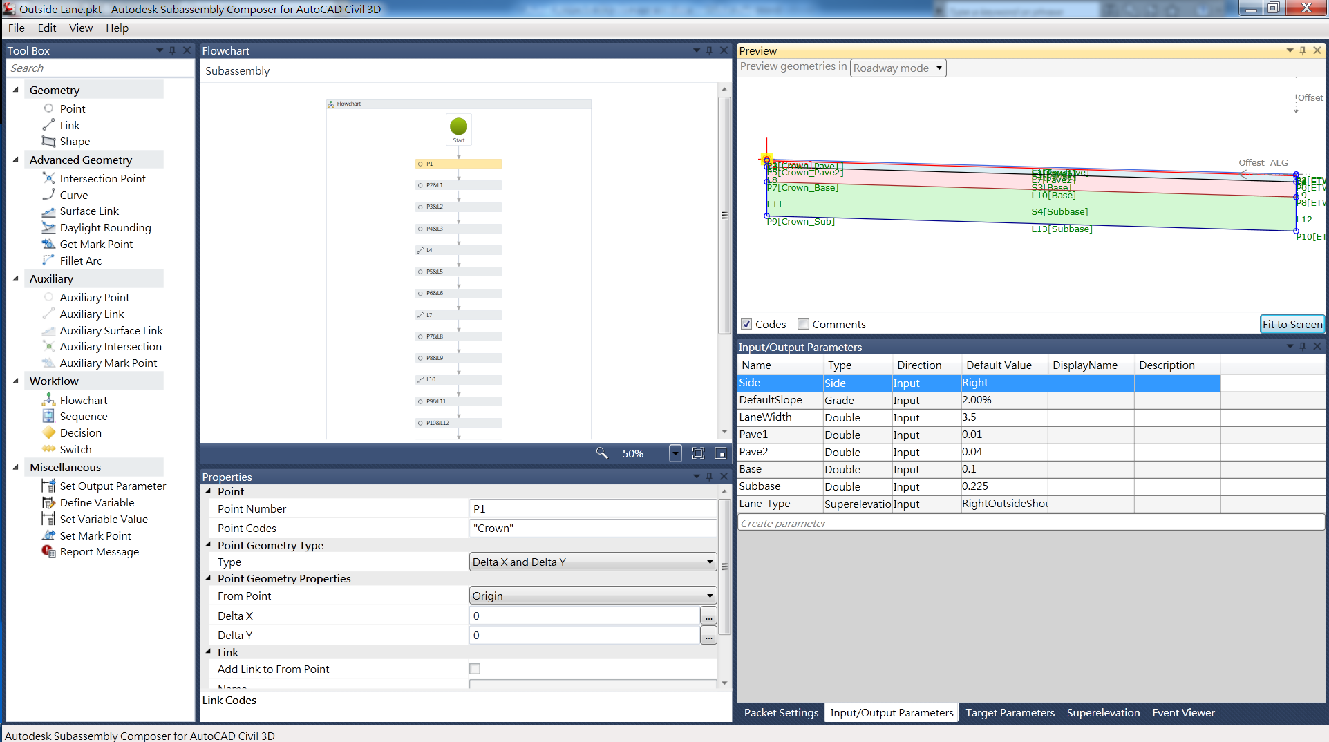
See image below. The left hand side contains items in your tool box. If you're familiar with looking through the help menus of various 'out of the box' subassemblies, then many of these items will make sense to you. The center of the window contains the subassembly flowchart. This area helps you visualize how the tools chosen from the tool box relate to one another.
From a user standpoint, keeping things clean and organized will make creating a subassmebly much easier. The window directly below the flowchart contains the properties of the tools used. Simply click on an item, and the properties of that item show below. The lower right window contains several tabs.
The first tab, 'Packet Settings' allows you to add a subassembly name (referenced in Civil 3D tool space), description of the subassmebly (again referenced in Civil 3D tool space), a help file (PDF, DOCX, or other), and graphic image (for viewing in Civil 3D tool space). Note that the help menu currently does not work for custom subassemblies within Civil 3D; this is a known bug that has not been fixed as of yet. The next tab is for Input/Output paramters, these show up under subassembly properties, parameters tab within Civil 3D and allow the end user to enter custom values for the components designed in subassembly composer. The third tab is for Target Parameters such as surfaces, offset targets, and elevation targets. The fourth tab contains super elevation data should that be needed, and the last tab is for the event viewer. I have only dealt with the first three tabs thus far.
• Now press Volume + Volume – and power at the same time. • Now copy that dload folder to root for your sdcard. • Update process will start. Huawei p6 u06 firmware. • Put sdcard to you phone and power off your cell phone. • Now copy update.app file to dload folder that you downloaded in step 1.
The upper right window, called the preview, is probably one of the most helpful areas of the program. This area displays what the subassembly you are creating should look like, with a few limitations. Items I've noticed are when you apply a surface target, an offset targe, or an offset elevation target to the subassembly,the display changes per the preview settings, on the Target Parameters tab mentioned above.
Thus causing the display of the design subassembly to appear differently than you'd expect. I'd recommend adding offset and elevation targets into the subassembly design last to avoid this. The help menu of SAC is pretty good. It seems to be a forum where users can add information, yet with some sort of control as to what information is added. There are several packet files out there for download to visually see how to use each tool.
This was probably the best way that I learned how to use the program. Open up one of the PKT files and view the data, click through the various tools and notice the properties programmed for each. Another good method in learning the software is to try and create one of the simple 'out of the box' subassemblies within subassembly composer. Creating a Subassembly Firstly, in creating your own subassembly, you have to have a great inspiring idea. However, be sure to not pick something too difficult to handle, or you can quickly become disatissfied that your custom subassembly does not work. My first subassembly turned out to be too difficult to achieve at first, so I had to find another that I could actually complete. I have been using the Civil 3D subassembly BasicSideSlopeCutDitch subassembly for quite a while and have found it extremely useful in roadway design.
In more than one circumstance, engineers have requested that I carry the channel along the toe of the fill slope to pick up additional drainage (as shown in the image below). This can be a difficult process without the use of SAC, basically adding a corridor, then grading in an additional channel with grading groups or corridors, and pasting surfaces together. Thus I had the idea to recreate the BasicSideSlopeCutDitch, but modify it to include a channel in the fill section. The flowchart for this subassembly is shown in the SAC overview image above and basically begins with a point that would be the hinge point of the subassembly and setting a target surface in the target parameters (set the surface preview to something greater than 0, while point 1 should be a 0,0. Next add in an auxiallry point, auxillary tools are temporary calculation tools and do not show up in Civil 3D visibly.